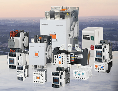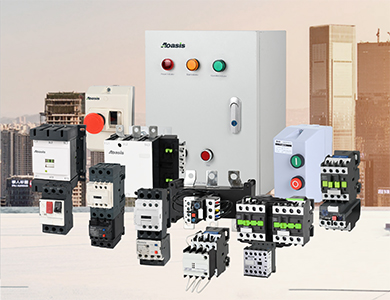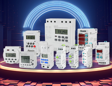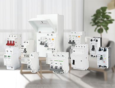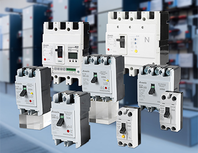
Focusing on product intelligence, energy-saving upgrades
We are an all-embracing style developing enterprise, integrating research, design, manufacturing, shipping and storing and marketing.
| Faliure phenomenon | Reason | Solution |
| Manually operated circuit breaker cannot be closed | 1. The undervoltage trip has no voltage or the coil is damaged | 1. Check the circuit, apply voltage or replace the coil |
| 2. The stored energy spring deformed, causing the closing force decreased | 2. Replace the stored energy spring | |
| 3. The counter-force spring force is too large | 3. Readjust the spring force | |
| 4. The mechanism can't be reset and then deducted | 4. Adjust and then deduct to the specified value | |
| Electrically operated circuit breaker cannot be closed | 1. The operating power supply voltage does not match | 1. Exchange power supply |
| 2. Insufficient power capacity | 2. Increase the operating power capacity | |
| 3. The electromagnetic rod stroke is not enough | 3. Re-adjust or replace the lever | |
| 4. Displacement of positioning switch for motor operation | 4. Readjust | |
| 5. The rectifier or capacitor damaged in the controller | 5. Change damaged components | |
| One phase contact can't be closed | 1. One connecting rod broken of general type circuit breaker | 1. Change the connecting rod |
| 2. The angle between the foldable connecting rods of the repulsion mechanism of the current-limiting circuit breaker becomes larger | 2. Adjust to the specified value of the original technical conditions | |
| The shunt trip can't make the circuit breaker break | 1. The coil is short-circuited | 1. Replace the coil |
| 2. The power supply voltage is too low | 2. Exchange the power supply voltage | |
| 3. Re-deduction contact area is too large | 3. Readjust | |
| 4. Loose screws | 4. Tighten | |
| The undervoltage trip cannot make the circuit breaker break | 1. The reaction spring becomes smaller | 1. Adjust the spring |
| 2. If the stored energy released, the stored energy spring will become smaller or broken | 2. Adjust or replace the stored energy spring | |
| 3. Mechanism stuck | 3. Eliminate the cause of the jam, such as rust | |
| The circuit breaker breakes immediately when starting the motor | The instantaneous setting value of the overcurrent trip is too small or selected incorrectly | 1. Adjust the instantaneous setting value |
| 2. If there is an air trip, the valve may fail or the rubber membrane may be broken. Replace it after finding out | ||
| After the circuit breaker closed, it will automatically disconnect in a certain time | 1. The long delay setting value of the overcurrent trip is incorrect | 1. Readjust |
| 2. Changes in thermal components or semiconductor delay circuit components | 2. Replace | |
| Undervoltage trip noise | 1. The counter-force spring is too large | 1. Readjust |
| 2. There is oil stain on the iron core working surface | 2. Eliminate oil stain | |
| 3. The short circuit ring broken | 3. Replace the armature or core | |
| Circuit breaker's high temperature | 1. The contact pressure too low | 1. Adjust the contact pressure or replace the spring |
| 2. Excessive abrasion or poorly contact on the contact surface | 2. Replace the contact or clean the contact surface, if it cannot be replaced, replace the entire circuit breaker | |
| 3. Connection screws loose of two conductive parts | 3. Tighten the screws | |
| 4. Contamination of Contact surface | 4. Remove oil stains or oxide layers | |
| Auxiliary switch doesn't work | 1. The moving contact bridge of the auxiliary switch is stuck or falls off | 1. Adjust or reinstall the contact bridge |
| 2. The auxiliary switch drive rod is broken or the roller falls off | 2. Replace the transmission rod or auxiliary switch | |
| 3. The contacts do not touch or oxidize | 3. Adjust the contacts and clean the oxide membrane | |
| Misoperation of circuit breaker with semiconductor trip | 1. The semiconductor trip element damaged | 1. Replace damaged components |
| 2. External electromagnetic interference | 2. Eliminate external interference, such as the operation of nearby large magnets, contactor disconnection, electric welding, etc., isolating or replacing the circuit | |
| Leakage circuit breakers often break automatically | 1.Changes in leakage action current | 1. Send to the manufacturer for re-calibration |
| 2.Leakage in line | 2. Find the reason, such as damage to the wire insulation, replace it |
| Fault phenomenon | Reason | Measure |
| Don't operate or operate unsteady | 1. The power supply voltage is too low or fluctuates too much. | 1. Increase the power supply voltage. |
| 2. Insufficient power supply capacity of the operating circuit or occurrence of disconnection, incorrect wiring and poor contact of control contacts. | 2. Increase the capacity of power supply , correct wiring, repair the control contact. | |
| 3. The control power supply voltage does not match with the coil voltage. | 3. Replace the coil. | |
| 4. The product itself is damaged (such as the coil is broken or burned, the movable part of the machine is stuck, the shaft is rusted or skewed, etc.) | 4. Replace the coil, exclude the stuck fault, repair damaged parts. | |
| 5. Contact spring's pressure and overtravel are too large. | 5. Adjust contact parameters as required. | |
| 6. The power supply is too far away from the contactor and the connecting wire is too thin. | 6. Replace the thicker connecting wire. | |
| Don't release or release too slow | 1. Contact spring's pressure is too small. | 1. Adjust the contact parameter. |
| 2. Contact fusion welding. | 2. Exclude the faults of fusion welding, repair or replace contacts. | |
| 3. The machine's movable part is jammed, and the shaft is rusty or skewed. | 3. Exclude the stuck phenomenon and repair the damaged part. | |
| 4. The counter-force spring is damaged. | 4. Replace the counter-force spring. | |
| 5. Have oil or dust on the pole surface of iron core. | 5.Clean up the pole surface of iron core. | |
| 6. E-shaped iron core, when its life is over, because the demagnetization air gap disappears and the remanence increases, make the iron core does not release. | 6. Replace the iron core. | |
| The coil is overheated or burned | 1. The power supply voltage is too high or too low. | 1. Adjust the power supply voltage. |
| 2. The technical parameters of coil (such as rated voltage, frequency, load factor and applicable working system, etc.) do not match with the actual usage conditions . | 2. Replace the coil or contactor. | |
| 3. Operating frequency is too high. | 3. Choose other suitable contactors. | |
| 4. The coil manufactured poorly or due to the mechanical damage, insulation damage, etc. | 4. Replace the coil and exclude the fault that causes mechanical damage to the coil. | |
| 5. Special environmental conditions for use: such as humid air, corrosive gas or high ambient temperature. | 5. Adopt the coil by specially designed. | |
| 6. The operating part is stuck. | 6. Exclude stuck phnomenon. | |
| 7. The pole face of the AC iron core is not flat or the demagnetization air gap is too large. | 7. Clean up the pole face or replace the iron core. | |
| 8. The AC contactor derives the DC-operated double coil. The coil is overheated because the normally closed interlock contacts are welded and not released. | 8. Adjust the interlock contact's parameters and replace the burnt coil. | |
| Electromagnet (AC)is noisy | 1. Power supply voltage is too low. | 1. Increase the operating circuit voltage. |
| 2. The contact spring pressure is too large. | 2. Adjust the contact spring pressure. | |
|
3. The magnetic system is skewed or stuck, making the iron core can't be suck flat. |
3. Exclude the fault of machine stuck. | |
| 4. The pole surface is rusty or foreign matter (such as grease, dust) adheres to the pole surface of the iron core. | 4. Clean up the pole face of the iron core. | |
| 5. Short circuit loop broken. | 5. Adjust the iron core or short circuit ring. | |
| 6. Excessive abrasion and unevenness of the core pole surface. | 6. Replace the iron core. | |
| Contact fusion welding | 1. The operating frequency is too high or the product's usage is overloaded. | 1. Adjust the appropriate contactor. |
| 2. Side short circuit of the load. | 2. Eliminate short-circuit faults and replace contacts. | |
| 3. Contact spring's pressure is too small. | 3. Adjust contact spring's pressure. | |
| 4. Protruding metal particles or foreign objects on the contact surface. | 4. Clean the contact surface | |
| 5. The operating circuit voltage is too low or mechanically stuck, resulting in stagnation during the pull-in process, and the contact stops at the position where it just touched. | 5. Increase the operating power supply voltage, eliminate the mechanical jam failure, and make the contactor suck reliably. | |
| Overheated or burned contacts in the eight-hour working system | 1. Contact spring's pressure is too small. | 1. Increase contact spring's pressure |
| 2. There is oil stain or the surface is uneven, and metal particles on the contact. | 2. Clean the contact surface | |
| 3. The ambient temperature is too high or used in a closed control box. | 3.Reduced usage specification of contactor | |
| 4. Copper contacts are used for long-term working ststem. | 4.Reduced usage specification of contactor | |
| 5. The overtravel of the contact is too small. | 5. Adjust the contact overtravel or replace the contact | |
| Excessive abrasion of contacts in a short time | 1. The contactor is not selected properly, and the capacity is insufficient in the following situations: | 1. Reduce the specifications of the contactor or switch to a contactor suitable for heavy tasks |
| (1)Forward and reverse control. | ||
| (2) There are more close operations. | ||
| (3) The operating frequency is too high. | ||
| 2. Three-phase contacts are not in contact at the same time. | 2. Adjust until the contacts touch at the same time | |
| 2. Side short circuit of the load. | 3. Eliminate short-circuit faults and replace contacts. | |
| 4. The contactor cannot be reliably closed. | 4. See solutions for unreliable actions. | |
| Short circuit | 1. The mechanical interlock of the reversible switching contactor is not reliable, and the two contactors are put into operation at the same time due to misoperation, causing a short circuit between phases, or because the contactor moves too fast, the switching time is short, so that arc short circuit occurs during the switching process. | 1. Check electrical and mechanical interlock; add intermediate links on the control circuit to prolong the reversible conversion time. |
| 2. Dust accumulates or sticks moisture, grease, make the insulation damaged. | 2. Clean up often, keep it clean. | |
| 2. Dust accumulates or sticks moisture, grease, make the insulation damaged. | 3. Replace damaged parts. |
| Fault phenomenon | Diagnosis | Handling method |
| The motor burns out and the thermal relay does not operate | 1. The setting current of the thermal relay is set too large. | 1. Adjust the setting current value according to the rated working current of the motor. |
| 2. The thermal element of the thermal relay is desoldered or burn out. | 2. Exit operation and send to professional manufacturer for repairing. | |
| 3. The operating machine is stuck. | 3. Exit operation and send to professional manufacturer for repairing. | |
| 4. The upper guide plate comes out. | 4. Reinstall and check flexibility. | |
| The thermal relay moves too fast | 1. The setting current is too small. | 1. Reasonably set the setting current value. If the setting current range of the thermal relay does not include the required setting value, replace the thermal relay specification. |
| 2. Motor starting time is too long. | 2. Change to the other trip class of thermal relay. | |
| 3. The connecting wire section is too small. | 3. Use the side-connected wire with the cross-section specified in the table above. | |
| 4. Strong shock and vibration. | 4. Take anti-vibration measures. | |
| 5. Reversible operation and close connection and disconnection. | 5. Change to other protection methods. | |
| Unstable movement | 1. The wiring screw is not tightened. | 1. Tighten the wiring screws. |
| 2. The power supply voltage fluctuates too much, and the quality of the distribution voltage is poor. | 2. Install a power regulator to improve the quality of power supply voltage. | |
| Thermal element burn out | 3. Sise short circuit breaker of load. | 3.Install short-circuit protection appliances on the power supply side of the thermal relay according to the requirements of coordination with SCPD. |
| The main circuit is not energized | 1. The wiring screw is not tightened. | 1. Tighten the wiring screws. |
| 2. The thermal element burns out. | 2. Replace the thermal relay. | |
| The auxiliary circuit is not powered | 1. There is oil stain on the contact surface. | 1. Remove oil stain on the contact surface. |
| 2. The rated working voltage of the auxiliary circuit is too low. | 2. Increased the rated working voltage of auxiliary circuit . |
| Failure phenomenon | Reason |
| 1. No response after power on. | 1. The transformer is damaged. |
| 2. Improper use caused product damaged. | |
| 3. The socket contacts poorly. | |
| 2. The setting error exceeds the standard. | 1. The working power frequency is incorrect (products that use the power frequency as the signal source). |
| 3. No show. | 1. The luminous tube is damaged. |
| 2. The digital tube shows that control circuit part is faulty. | |
| 4. The show is abnormal | 1. Clear and pause lead is too long. |
| 2. The anti-interference line occurs faults. | |
| 3. Clear and pause lead wires do not use shielded wires (with higher interference sources). | |
| 4. The digital tube is damaged. | |
| 5. No conversion after delay stop | 1. The power supply voltage is too low. |
| 2. The actuator occurs faults. |
| Failure phenomenon | Cause | Solution |
| The starting cabinet does not work | 1. The starting cabinet out of power. | 1. Electricity transmission. |
| 2. Thermal relay operates. | 2. Find out the cause and reset. | |
| 3. The contactor coil burns out. | 3. Replace the coil. | |
| The contactor is difficult to suck and rebound | 1. The input voltage is too low. | 1. Try to increase the input voltage and reduce the line voltage drop. |
| 2. Insufficient power supply. | 2. Increase the capacity of the power supply transformer. | |
| Starting hard | 1. Low input voltage. | 1. Improve the input voltage. |
| 2. Overload. | 2. Reduce the starting load. | |
| No conversion after starting automatically | 1. Current-time conversion device occurs faults. | 1. Find out the fault and repair it. |
| 2. The current-time conversion device set incorrectly. | 2. Read the manual carefully, adjust and set correctly. | |
| No conversion after manual switching | 1. The manual control secondary circuit occurs malfunction. | 1. Find out the fault and repair it. |
| 2. The main contact of the starting contactor is bonded. | 2. Cut off the power immediately. Check whether the load is too heavy, the capacity of the power supply transformer is insufficient, and the voltage drop is too large. | |
| Autotransformer humming | 1. The iron core of transformer is not clamped. | 1. Clamp the iron core of transformer. |
| 2. There is a coil short circuit to the ground in the transformer | 2. Use a megohmmeter to find out the grounded coil, disassemble and rewind or add insulation to the damaged place. | |
| Motor overheating, thermal relay protection | 1. Overload. | 1. Try to reduce the load.. |
| 2. Load failure. | 2. Solve the appliance failure. | |
| 3. The motor runs that lacking phase. | 3. Pay attention to monitoring to prevent operating lack of phase. | |
| 4. High ambient temperature. | 4. Improve ventilation. | |
| 5. The line voltage is low. | 5. Increase the input voltage. | |
| The motor starts too fast | 1. Large torque of the motor. | |
| a. High tap voltage of the autotransformer. | 1. Adjust the tap. | |
| b. One or more coils short-circuited of the autotransformer . | 2. Use a megohmmeter to find out the grounded coil, disassemble and rewind or add insulation to the damaged place. | |
| 2. Wiring incorrect. | 3. Check the wiring between the motor and the starting cabinet, and check the wiring diagram in the manual. | |
| Contactor overheating or wiring pole overheating | 1. Low voltage, high circuit current. | 1. Improve the input voltage. |
| 2. The contact pressure is too small. | 2. Adjust the spring's pressure. | |
| 3. Contact burn out severely. | 3. Change the ablated contacts in time. | |
| 4. The pole surface moving core is dirty, and the coil is scratched or partly short-circuited with electric dust. | 4. Change the coil and keep it clean frequently. | |
| Electric appliances are noisy | 1. The reaction force of the contactor spring is too large | 1. Adjust the spring's pressure. |
| 2. There is dirt on the pole surface of the iron core of the contactor. | 2. Remove dirt. | |
| 3. Excessive abrasion and unevenness of the pole surface of the contactor. | 3. Correct the pole surface. | |
| 4. The contactor magnetic system is skewed. | 4. Adjust the mechanical part. | |
| 5. The contactor short-circuit ring is broken. | 5. Re-solder or replace the short-circuit ring. | |
| Phenomenon | Cause | Handling method |
| Circuit breaker short circuit does not operate | The selection is too large, and the rated current of the circuit breaker is much larger than the calculated load current of the line; | Replace the circuit breaker with a suitable specification; |
| The wire is too thin and does not match with the selected circuit breaker; | Select the wire which is suitable for the circuit breaker; | |
| The wire laying distance is too long. | Re-lay the line. | |
| The circuit breaker does not close the break | The load current is bigger than the rated current of the circuit breaker; | Choose the appropriate circuit breaker; |
| The wire is too thin, does not match with the selected circuit breaker, the circuit resistance increases, and the circuit breaker temperature rises | Select the wire which is suitable for the circuit breaker; | |
| Short circuit or leakage at the load end; | Exclude malfunction | |
| Product damaged. | Change the circuit breaker. | |
| Burnt out of the shell at the wiring terminal | The terminal is not tightened or the terminal slips | Replace the product. After wiring, pull the wire by hand to fasten it. |

